Pool & Spa News Online - Coverups
Crafty ideas for making pools with automatic covers look and function even better.
By Paul Benedetti August 2003
Special to Pool & Spa News
 ome of my wealthiest clients love the benefits that automatic covers offer — all the safety, energy and chemical savings, along with the extra convenience.
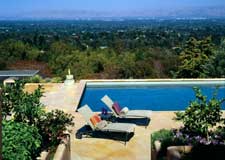
But people who spend hundreds of thousands of dollars on an aquascape don’t accept the aesthetic limitations of covers. I’ve had more than one customer who said, “When it’s open, I don’t want to know it’s there.”
Over time, I’ve developed several ways of concealing the “evidence,” with the help of my cover manufacturer.
Of course, innovation such as this is a never-ending process. Some of the details I’m sharing are in various stages. Most are finished pools, some are in construction and one is still in the drawing stage.
In-wall receiver
Until recently, using an automatic cover limited the kind of coping we could use. The track mounted to the coping, so the stone needed to cantilever sufficiently into the pool and be thick enough to put 1-1/2-inch screws into the underside. We couldn’t use a 1- or 2-inch tumbled stone or anything petite. If the drilling didn’t shatter the thin coping, weight from traffic would.
Recently, several manufacturers solved that problem. They now offer an in-wall receiver receiver to hold the track assembly. This way, the track is actually embedded in the pool wall, so the weight is taken off the coping — and you can choose whatever coping material you want.
The channel attaches to the top of the bond beam, so the track still sits right under the coping. It should be installed before any tile or masonry go in. You want it to sit flush with the tile, just above it. Protrude it from the gunite enough to allow for the float and tile. The top of the tile line should butt up against the channel. Then set the coping of your choice on top of the channel.
Remember, during construction, you need to build the bond beam about 1 to 1-1/2 inches shorter than normal to allow for the channel. When you bolt the receiver to the top, you’ll have the normal elevation.
The pool ends will still be shorter than the final elevation, though. Usually, the masonry crews will add extra mortar before installing the coping to even everything out.
But then you have a 3/4- to 1-inch joint between the tile line and the coping on the end of the pool opposite the cover vault. You can’t leave this fat grout joint showing, so you need to fill the space with something. We use either little slices of tile from the tile line or some other type of trim to clean it up. (The masons love me for that!)
In one project, for instance, we had used 1-inch mosaic tiles on the tile line. Obviously, grinding 1/4-inch off hundreds of little tiles would take forever. Instead, we used the flagstone that made up the coping. Each 3/4-inch strip was 2 feet long, so the joints would line up with the coping joints. It gives the appearance that the stone decking comes down and has a unique detail on the end of the pool.
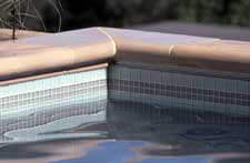
When all is said and done, you’ll see a little silver rail that’s flush with the tile rather than a grout line and mud between the tile and coping. Then cover installers push the track inside this slot.
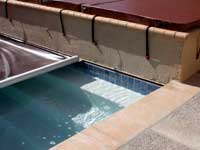
Flush, raised spa
The in-wall tracking allows us to do something else we couldn’t do before on a covered pool: Build a raised spa flush with the pool — or any raised bond beam, for that matter. Before, if you wanted a raised spa you either had to cantilever it 3 inches over the pool to mount the track underneath it, or you’d have to step it back enough to install coping on the pool. But the in-wall receiver accommodates a raised spa built flush with the pool.
I used this technique on a recent project. The client wanted the spa face to be flush with the pool wall. If the client had wanted to tile above and below the receiver, no problem — the receiver would just look like a fatter grout joint. After considering tile, however, this client chose stucco for the raised wall.
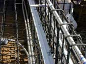
Balancing act: When building the raised spa, crews had to carefully bolt the in-wall receiver onto the steel so it wouldn't budge during guniteing.
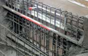
In this case, we couldn’t just bolt the receiver into the top of the bond beam. We had to gunite it right into the wall. Because we couldn’t use the top of the bond beam as a guide, we had to know exact elevations ahead of time. Otherwise, the track on both sides of the pool wouldn’t line up.
We also had to find a way to keep the receiver from moving during the gunite phase. If we had just drilled holes and used regular tie wire, the thing would have dropped right down like a hinge. So we drilled holes in the flange behind the receiver, and put threaded stainless steel rods through the flange holes. We sandwiched the flange with nuts and washers, then bent the rods over so we could tie them to the steel. The rods also electrically bonded the receiver to the steel.
On the project pictured, it must have taken 30 rods to keep it in place. We taped over the front of the receiver (the opening) so it didn’t get clogged during guniting.
This was the first time this has ever been done. So the vice president of operations for our cover manufacturer looked at it before gunite.
He double-checked the elevations and made sure that we had extended the receiver past the pool wall about 6 inches or so. The cover installers usually end up cutting a few inches off, but this way they have more than enough to slide the track and end pulley under the coping.
This detail will work any time you do a raised bond beam, whether it’s for a planter, a waterfall or just because you’ve got an elevated deck area.
Masonry lid
I don’t use metal lids on my cover box. Never have, never will. And my clientele won’t accept them. Such lids are ugly, and you can’t walk on them because they bend and burn your feet. So you lose part of the foot traffic area.
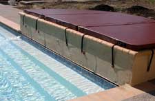
I always conceal the cover box with the same material we use on the deck. It looks much better and people can walk on the lid. This adds thousands of dollars to the job, but it makes so much sense, practically and aesthetically.To do this, you need a masonry tray setup to support the mortar or to pour the material on. The brackets are configured like the ones you use for cheap shelf units, but really beefed up with a big L with a diagonal support going across. The brackets themselves measure about 12-by-12-inches. You mount them inside the back wall of the cover box, spaced every couple feet. The cover roll sits underneath the brackets. Of course, we install a joint separating the cover box from the deck, so they can move independently of each other.
Several stainless steel trays go across the cover box, on top of the brackets. These will hold your masonry. You can specify whatever tray width you want to fit the masonry. Usually they’re 12-, 16- or 18-inches wide. The tray either rests on the brackets or hooks on a hinge pin. The trays have a stainless steel mesh on top of them, which will grab the mortar or concrete for better adhesion. You can mortar bricks or stone, or make poured-in-place coping right on top of the trays.
A lot of builders will stop the deck behind the back wall of the cover box. Then they put coping on the trays, and they’re left with a little 6-inch gap over the back wall of the box. If they’re using brick coping, they might run one or two extra courses behind the coping to cover the back wall. But it doesn’t look balanced: When you look out from the house, you see a single band of bricks around three sides of the pool, then a double or triple row of bricks on one end.
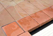
To avoid this problem, we install a single row of coping stone over the cover box. Then we continue the decking material across the back wall of the cover box, onto the trays and right up to the coping. We’ll even do this with flagstone. They’ll set and grout between the stones as if it were all one large span of deck.
Then we go back and saw cut the joints. Two long joints span the cover-box width — one separating the back wall of the cover box from the deck; one between the front of the cover box wall and the row of trays. Then we cut a joint between each tray so they remain independent of each other. From a distance, you might not see the joints, or you might see only a faint line.
A masonry cover box is done after the pool is completed, so you have to pay extra for the masons to make an another trip. It ends up being a lot of additional work, but from the aesthetics and functionality standpoints, it’s kind of a no-brainer.
When the box is covered by the deck material, almost all evidence of the box is covered up — almost. Usually, swimmers can see this little silver line underneath the coping where the tray is. If you want to, you can hide the evidence.
To conceal this detail, I make the stone or coping hang slightly over the front of the tray. The crews use a masonry saw to notch the stone or coping. Because the trays are 1/2-inch thick, they’ll make the notch 3/4- to 1-inch deep. The notch sits about 1-1/2- to 2 inches behind the front of the stone. It’s easier to do this on thicker stone because you can get a good reveal underneath without cracking it. You have to be a little careful with bricks, though, because they’re only 2-1/2-inches thick. If you try to notch it too much, it’ll crack the brick.
Hidden lead barAnother slightly annoying detail is how the lead bar shows when the cover’s open or closed. (Like I said, I deal with choosy clients.) When the cover’s open, the lead bar stops right in front of the masonry trays; when the cover’s closed, it stops right at the coping on the other side of the pool.
I wanted to hide that lead bar, whether the cover was open or closed. I wanted it under the coping when it’s closed and under the masonry trays when it’s open. That means slightly lowering the elevation of the lead bar.
To allow this, we start by creating a notch on top of the cover dam. The notch runs along the dam’s length, at the front of the wall. Remember, we run the waterline 2 inches lower than normal. We make the notch 2 inches deep, so the bottom is flush with the waterline. This will allow the lead bar to pull slightly underneath the masonry trays, rather than sticking out when it hits the cover dam.
We also want to drop the lead bar a little. The trick is in how we install the brackets that mount the lead bar to the track on either side. Normally, that bracket puts the lead bar at coping elevation, so the bar bumps right into the coping when the cover is closed. We install the brackets upside down. By doing this, we lower the elevation of the lead bar just a touch, making it tuck right underneath the coping at the opposite end of the cover box. When it opens, the lead bar glides into the notch we’ve created on the dam wall, just under the cover box lid.
As a finishing touch, we always apply powder coating to the hardware to match the coping.
Now, instead of having a big, shiny bar showing, you lose one more piece of evidence that the pool has a cover.
Paul Benedetti is vice president of Aquatic Technology Pool & Spa in Morgan Hill, Calif. The former service technician now specializes in the design and construction of high-end aquascapes. He has taught courses about intricate aquascape design and is an associate member of Genesis 3. Benedetti is a subject-matter expert for the state of California and assisted in writing California’s most recent pool contractor’s examination.
© 2003, Pool & Spa News